Language
 English
English
English
Features
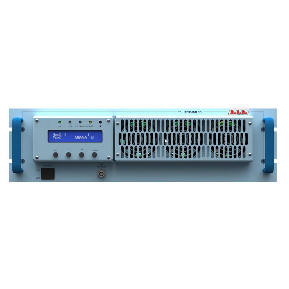
The overall efficiency of TEX3500LCD is better than 70% across the bandwidth, for this reason are part of RVR Green Line family. This performance characteristic is guaranteed in a range between +0.25 dB and -3 dB (+5% and -50%) referred to the nominal power of the equipment: for example from 1750W to 3675W in case of TEX3500LCD; outside these limits the equipment is able to work properly but can not guarantee an efficiency of 70%. This transmitter incorporate a low-pass filter to keep harmonics below the limits provided for by international standards (CCIR, FCC or ETSI) and can be connected directly to the antenna. Two major features of TEX3500LCD is compact design and user-friendliness. Another key feature is its modular-concept design: the different functions are performed by modules with most connections achieved through male and female connectors or through flat cables terminated by connectors. This design facilitates maintenance and module replacement. The RF power section of TEX3500LCD uses one LD-MOSFET module delivering up to 900W output power.
Operating frequency stability is ensured by a temperature-compensated reference oscillator and is maintained by a PLL (Phase Locked Loop) system. The transmitter will go into frequency lock within 30 seconds after power-on. TEX3500LCD can operate throughout the frequency bank with no need for calibration or set-up. An LCD on the front panel and a push-button panel provide for user interfacing with the microprocessor control system, which implements the following features:
• Output power setup.
• Working frequency setup.
• Power output enable/disable.
• User-selectable threshold settings for output power alarm (Power Good feature)
• Measurement and display of transmitter operating parameters.
• Communication with external devices such as programming or telemetry systems via RS232 serial interface or I2 C. Four LEDs on the front panel provide the following status indications: ON, LOCK, FOLDBACK and RF MUTE. The transmitter management firmware is based on a menu system. User has four navigation buttons available to browse submenus: ESC , , , ed ENTER. The rear panel features the mains input connectors, as well as audio input connectors and RF output connector, telemetry connector, protection fuses and two inputs for signals modulated onto subcarriers by suitable external coders, such as RDS (Radio Data System) signals commonly used in Europe.
Specifications
|
TEX3500LCD |
||||
|
Parameters |
|
U.M. |
Value |
Notes |
|
GENERALS |
|
|
|
|
|
Frequency range |
|
MHz |
87,5 ÷ 108 |
|
|
Rated output power |
|
W |
3500 |
Continuously adjustable from 10 to 100% |
|
Modulation type |
|
|
F3E Direct carrier frequency |
|
|
Operational mode |
|
|
Mono, Stereo, Multiplex |
|
|
Working temperature |
|
°C |
-5 to +50 |
|
|
Working humidity |
|
% |
95 |
Without condensing |
|
Working altitude |
|
mt |
Up to 2000 * |
* With adequate air evacuation system in site |
|
Frequency setting |
|
kHz |
10 |
Steps |
|
Frequency stability |
Temperature range from -5°C to 50°C |
ppm |
±1 |
|
|
Modulation capability |
Refered @ 0dBu for 75kHz |
kHz |
150 Stereo, 180 Mono/MPX |
Meets or exceeds all FCC and CCIR rules |
|
Pre-emphasis |
|
µS |
0, 50 (CCIR), 75 (FCC) |
Selectable |
|
POWER REQUIREMENTS |
|
|
|
|
|
AC Power input |
AC Supply Voltage |
VAC |
230 +10% -15% | 400 +10% -15% |
Monophase | Threephases Y |
|
|
AC Apparent Power Consumption |
VA |
4996 |
|
|
|
Active Power Consumption |
W |
4987 |
|
|
|
Power Factor |
|
0,998 |
|
|
|
Overall Efficiency |
% |
Typical 70 |
|
|
|
Connector |
|
Terminal Block |
|
|
MECHANICAL DIMENSIONS |
|
|
|
|
|
Phisical dimensions |
Front panel width |
mm / inch |
483 / 19 |
EIA rack |
|
|
Front panel height |
mm / inch |
132 / 5 1/4 |
3HE |
|
|
Overall depth |
mm |
675 |
|
|
|
Chassis depth |
mm |
650 |
|
|
Weight |
|
kg |
About 29 |
|
|
Cooling |
|
|
Forced, with internal fan |
|
|
Acoustic noise |
|
dBA |
< 75 |
|
|
AUDIO INPUTS |
|
|
|
|
|
Left / Mono |
Connector |
|
XLR F |
|
|
|
Type |
|
Balanced |
|
|
|
Impedance |
Ohm |
10 k or 600 |
|
|
|
Input Level /Adjust |
dBu |
-13 to +13 |
Continuosly adjustable |
|
Right |
Connector |
|
XLR F |
|
|
|
Type |
|
Balanced |
|
|
|
Impedance |
Ohm |
10 k or 600 |
|
|
|
Input Level |
dBu |
-13 to +13 |
Continuosly adjustable |
|
MPX |
Connector |
|
BNC |
|
|
|
Type |
|
Unbalanced |
|
|
|
Impedance |
Ohm |
10 k or 50 |
|
|
|
Input Level /Adjust |
dBu |
-13 to +13 |
For 7,5 KHz FM, adjustable |
|
SCA/RDS |
Connector |
|
2xBNC |
|
|
|
Type |
|
Unbalanced |
|
|
|
Impedance |
Ohm |
10 k |
|
|
|
Subcarier Level @ 0 dBu |
dB |
-17 to -40 |
For 7,5 KHz FM, adjustable |
|
AES/EBU (optional) |
Connector |
|
XLR F |
|
|
|
Type |
|
Balanced |
|
|
|
Impedance |
Ohm |
110 |
|
|
|
Input Level /Adjust |
dBfs |
0 to -10 |
For 7,5 KHz FM, adjustable |
|
TOS/Link |
|
|
TOS-Link |
|
|
|
|
|
Optical |
|
|
OUTPUTS |
|
|
|
|
|
RF Output |
Connector |
|
7/8" EIA |
|
|
|
Impedance |
Ohm |
50 |
|
|
RF Monitor |
Connector |
|
BNC |
|
|
|
Impedance |
Ohm |
50 |
|
|
|
Output Level |
dB |
Approx. -60 |
|
|
Pilot output |
Connector |
|
BNC |
|
|
|
Load Impedance |
Ohm |
>5 K |
|
|
|
Output Level |
Vpp |
1 |
Sinusoidal |
|
FUSES |
|
|
|
|
|
On mains |
|
|
3 External F 10 T - 6 x 30 mm |
|
|
On services |
|
|
X |
|
|
On PA Supply |
|
|
4 Internal F 32 A 10 x 38 mm |
|
|
On driver supply |
|
|
X |
|
 Español